Autonomous vehicle: Simple collision prevention
After adding camera support and remote control to the chassis, I found that accurate driving of RC car is not a trivial thing and quite often while driving I am hitting different obstacles like walls, tables, doors. So I decided to add some sensors to detect and avoid obstacles.
I had Arduino UNO, which I bought a few years ago, and decided to build a solution using it. A quick search on the Internet has shown a few ways to do it for the various price ranges. I chose to try one of the cheapest.
Ultrasonic sensor HC-SR04
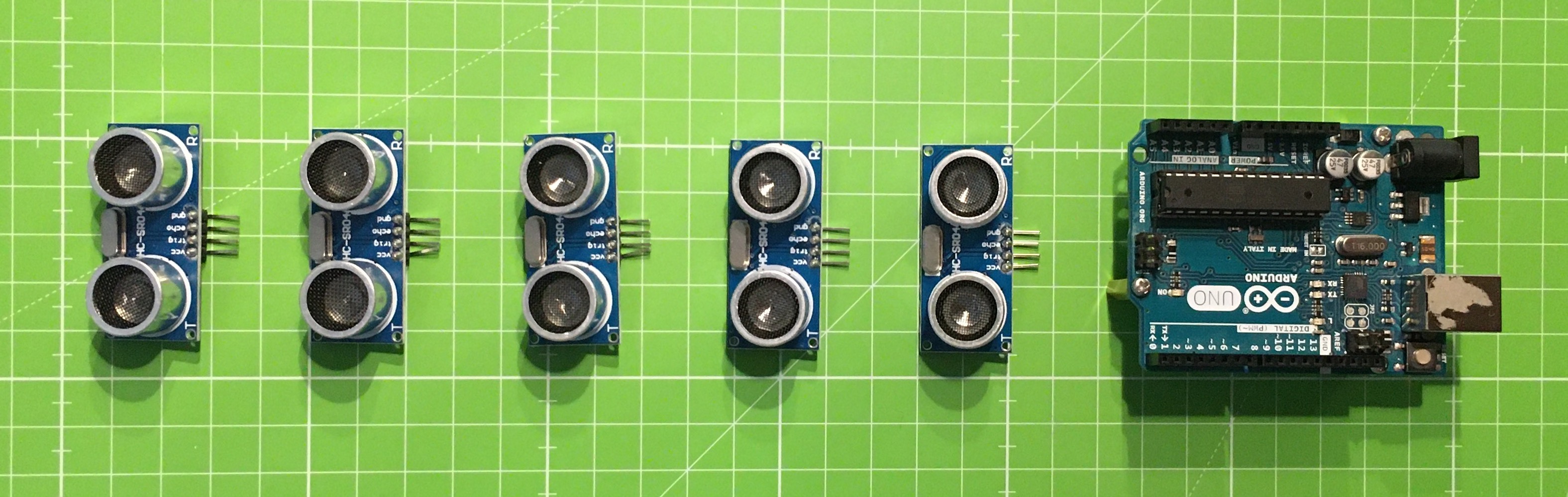
I bought I pack of ultrasonic sensors HC-SR04, which are cheap and have a pretty simple and straightforward way of measuring distance. They emit impulse of the high-frequency sound and receive a reflected signal. After measuring the duration between these two events, it is possible to calculate a distance, assuming that we know the speed of the sound. To be correct, to measure a distance precisely, duration is not enough, we also have to consider the environmental temperature and humidity, but for my task, I decided to skip them.
I mounted three of the sensors in front of my RC car in the following way:
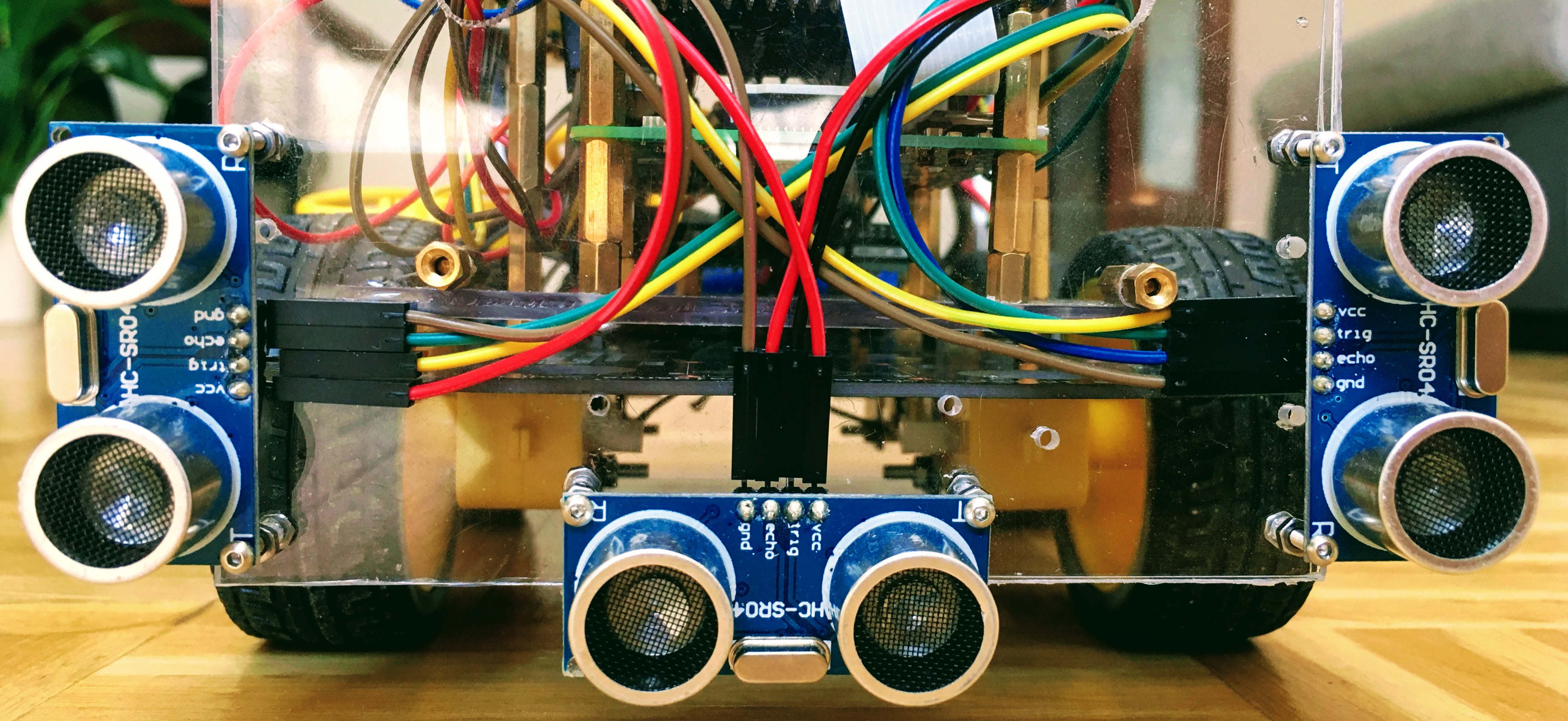
Also I decided to connect Arduino to the Raspberry Pi via USB. Doing it like that, I can provide power to the Arduino board and, at the same time, use it as a serial port to get the sensor’s values.
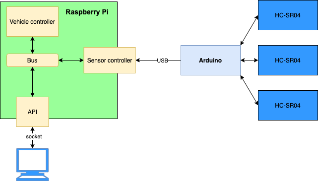
On Raspberry Pi’s side, because I already had a code to control the engine of my RC car, I decided to write a few more modules using the python to handle a sensor’s data. Also, I wanted to run each part in a separate thread or process using multiprocessing and thread modules.
Finally, the Raspberry Pi’s part had four main components:
- Vehicle controller, a modified version of the code from here. It is responsible for receiving and executing commands like move, stop, drive, increase, and decrease speed.
- Bus, simple router to deliver messages and commands between processes and threads.
- Sensor controller is responsible for collecting measurements from Arduino and analyzing them.
- API, simple socket-based API can listen to driving commands and report the current system state to the outer clients.
Arduino, in this system, is collecting data from the sensors and sending it to the Raspberry Pi.
First test
To have some observation of how my RC car sees the world, I created a simple GUI to render the sensor data. I used matplotlib and connected it to the API I have created before. After the first test, I saw the following result:
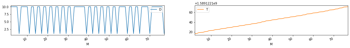
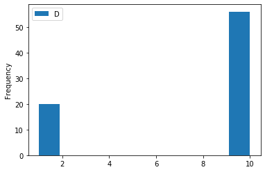
The blue box in the middle is chassis; the lines above represent measurements from three sensors. It shows that they are oscillating a lot. I did some more experiments with the following results:
Distance (D) ~10 cm, Measurement number (M), Time (T):
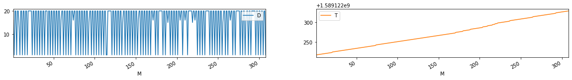
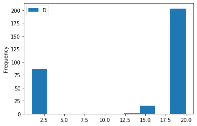
Distance (D) ~20 cm, Measurement number (M), Time (T):
Data filtering
As is shown in the graph, there are many false measurements. I tried to implement filter by using the median for the subset of sequential measurements, but to get good results, I had to make a size of subsets pretty big. In this case, the system was unable to react to the obstacles which were approaching relatively fast.
Possible reasons
I failed with an initial try and thought about the possible reasons for such sensor’s behavior. I had three hypotheses about it:
- Sensors quality. I am using cheap sensors. They might be quite noisy.
- Bad sensors setup. Because all the sensor uses the same frequency to do a measurement, they can interfere with each other. The speed of sound is comparatively low, so it can be that the next sensor is getting the echo from the distant objects which are reflecting the waves from the previous one.
- Bad wiring. I have to use relatively long wires to interconnect the Arduino and sensors and power supplies. And all these wires lay close to the other components which have a magnetic field, like motors.
New sensor
To validate my first hypothesis, I bought the same sensor from a different manufacturer, which has a lot of positive reviews and recommendations. Unfortunately, the result was almost the same.
Sensor’s setup
There are two moments that I considered about sensor’s setup. First, it is layout geometry, and second is how the measurements are programmed. All sensors are “looking” forward, which is something that I want and make it differently makes no sense to me. The coding part was straightforward. It is just copy-paste from the most popular examples of how to use HC-SR04, similar to:
void loop() {
  digitalWrite(trigPin, LOW);
  delayMicroseconds(5);
  digitalWrite(trigPin, HIGH);
  delayMicroseconds(10);
  digitalWrite(trigPin, LOW);
  dur = pulseIn(echoPin, HIGH);
  distance = dur * 0.034 / 2; // in cm
  delay(50);
}
I tried to change delays, but it didn’t work well for me: measurements became very sparse, or results were still noisy.
After some research on the Internet and reading the posts from the people who had the same issue, I found the lib NewPing which is providing a great set of the features, like making the measurements and doing basic filtering. Also, it provides a good interface, and what is more important, it solved my problem with noise. More info about the lib you can find in it’s wiki.
After I started to use this lib, I was able to get stable measurements.
Conclusion
I achieved a goal. My RC vehicle can detect the obstacles and react to this detection and, as a result, avoid a collision. I learned a lot about multiprocessing and threading in python3 by implementing a sensor’s data analysis in “real-time”. Also, I learned that “real-time” is not always real-time. Small delays in transferring critical data between threads and processes might become a problem when the RC car is moving relatively fast. And one more thing: hardware is not the only component required to a proper measurement, the way how they are programmed is very important too.