Autonomous vehicle: The Speed
There are some ideas about how to build a remote control vehicle in previous article. But it lacks an important feature: the speed control.
One of the possibilities to control the speed using the existing prototype is PWM method.
Goal
To make a RC vehicle that drives with constant speed, capable of driving with adjustable speed using PWM.
Idea of PWM
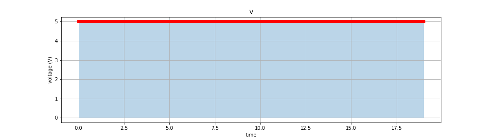
The voltage we have on GPIO has only two values: 0V and 3.3V. That means that our DC motor either stops or driving on full throttle. The following chart represents this states:
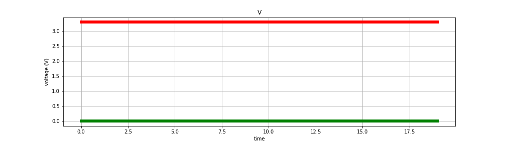
The red line shows the voltage when we turn on the motor and moving. Green when we turn off it and stop.
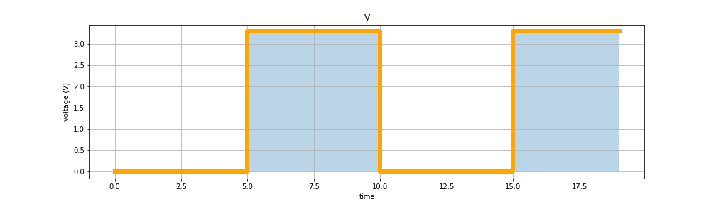
The idea of controlling speed via PWM is to change frequently on and off states. For instance: if during the same period, we turn off and turn on the power twice and so corresponded chart looks like:
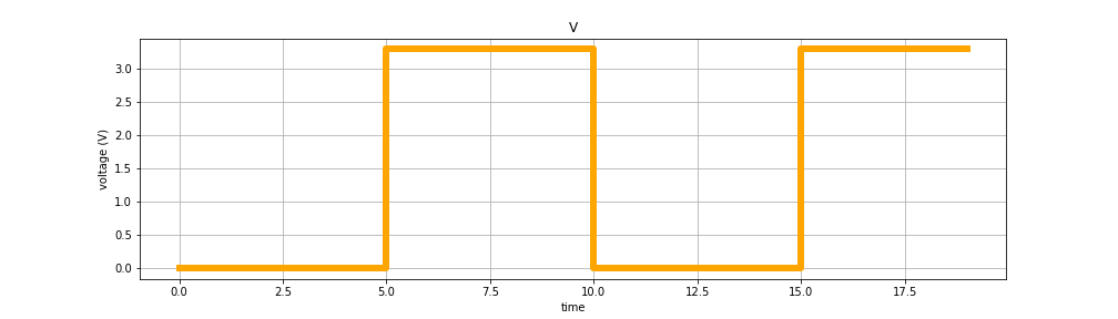
Half of the time, the motor was off, and half is on, so the vehicle passes only half of the way comparable to the situation if it would be working at full power all the time. It should give some intuition about the basic idea.
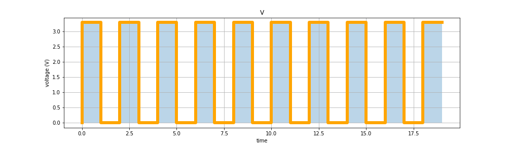
Of course, if you make this period of work and idle state too long, you will see that the vehicle goes with jerks. To tackle it we have to achieve the chart of voltage change similar to this:
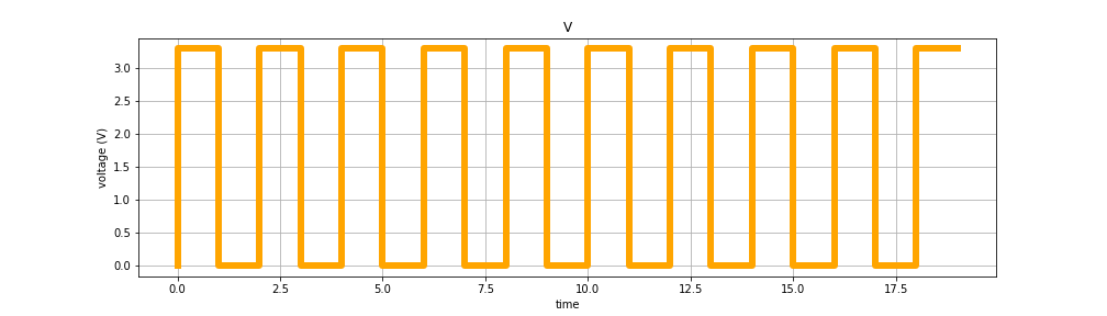
States are changing very often, and because of the inertia of the car and motors, it is continuously moving, but with reduced speed.
The length of the path car drive proportional to the area under the line:
Pic 1:
Pic 2:
Pic 3:
PWM uses two parameters to transform current from the Pic 1 to Pic 2 or Pic 3. The first parameter, called Duty Cycle and Frequency.
-
Frequency defines the period between two lines goes up. For instance, in
Pic 2it is the time between5.0and15.0 -
Duty Cycle defines how long the motor is on during this period. For instance, in
Pic 2it is 50% of the time. A higher percentage means a longer period, which in turn means higher speed.
The code
Based on the knowledge about PWM, let’s add speed control to our RC car.
import RPi.GPIO as GPIO
import getch
import sys

print("start")

# Change the mode to the BCM, to use known GPIO's mapping
GPIO.setmode(GPIO.BCM)

# Define a constants to have a reasonable names for the GPIOs
ENA = 13
ENB = 20
IN1 = 19
IN2 = 16
IN3 = 21
IN4 = 26

# Set the initial state for the GPIOs: mode OUT, value LOW
GPIO.setup(ENA, GPIO.OUT, initial=GPIO.LOW)
GPIO.setup(ENB, GPIO.OUT, initial=GPIO.LOW)
GPIO.setup(IN1, GPIO.OUT, initial=GPIO.LOW)
GPIO.setup(IN2, GPIO.OUT, initial=GPIO.LOW)
GPIO.setup(IN3, GPIO.OUT, initial=GPIO.LOW)
GPIO.setup(IN4, GPIO.OUT, initial=GPIO.LOW)

# Turn on the motors, by setting signal to HIGH
GPIO.output(ENA, True)
GPIO.output(ENB, True)

# Create a PWM instance, with initial frequency
p1 = GPIO.PWM(ENA, 60)
p2 = GPIO.PWM(ENB, 60)

# Start PWM
p1.start(0)
p2.start(0)

# Set initial speed
speed = 0


# Rotate motors forward
def forward():
    GPIO.output(IN1, False)
    GPIO.output(IN2, True)
    GPIO.output(IN3, False)
    GPIO.output(IN4, True)


# Rotate motors backward
def backward():
    GPIO.output(IN1, True)
    GPIO.output(IN2, False)
    GPIO.output(IN3, True)
    GPIO.output(IN4, False)


# Right motor forward, left backward
def left():
    GPIO.output(IN1, False)
    GPIO.output(IN2, True)
    GPIO.output(IN3, True)
    GPIO.output(IN4, False)


# Left motor forward, right backward
def right():
    GPIO.output(IN1, True)
    GPIO.output(IN2, False)
    GPIO.output(IN3, False)
    GPIO.output(IN4, True)


# Set all GPIOs to low, to stop the vehicle
def stop():
    GPIO.output(IN1, False)
    GPIO.output(IN2, False)
    GPIO.output(IN3, False)
    GPIO.output(IN4, False)


# Increase speed by 10%
def increase_speed():
    global p1, p2, speed
    if speed < 100:
        speed += 10
        p1.ChangeDutyCycle(speed)
        p2.ChangeDutyCycle(speed)


# Decrease speed by 10%
def decrease_speed():
    global p1, p2, speed
    if speed > 0:
        speed -= 10
        p1.ChangeDutyCycle(speed)
        p2.ChangeDutyCycle(speed)


# Implement vehicle control
def switch(x):
    return {
        'w': lambda: forward(),
        's': lambda: backward(),
        'a': lambda: left(),
        'd': lambda: right(),
        'h': lambda: stop(),
        ']': lambda: increase_speed(),
        '[': lambda: decrease_speed(),
    }[x]


# Main loop
while True:
    # Read char from input
    char = getch.getch()
    try:
        # Try to find and run proper control
        switch(char)()
    except KeyError:
        # If unknown control was requested, stop the loop
        break
    print(f"\rspeed {speed}%", end="")
    sys.stdout.flush()

# Reset all GPIOs configured by this command
GPIO.cleanup()

print("end")
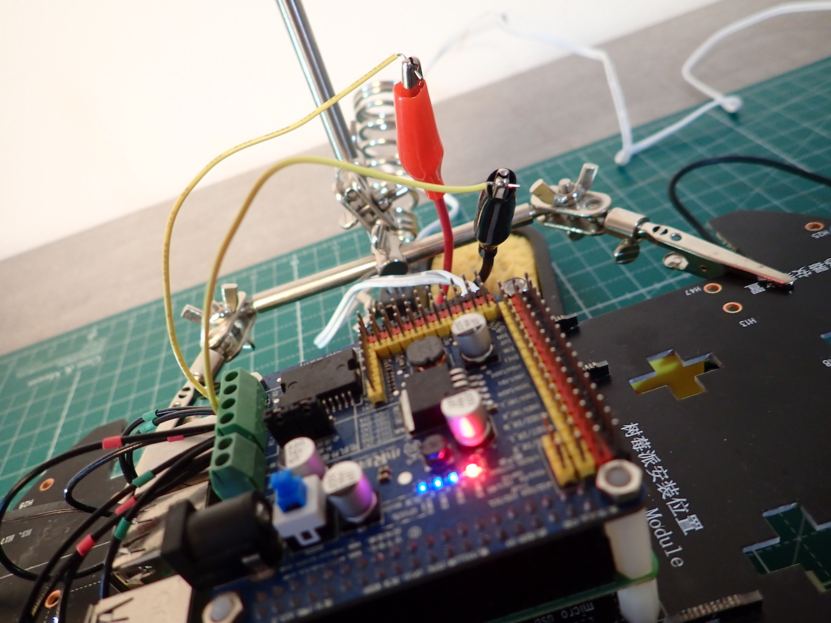
Demo
Here is a demonstration of using PWM to control the speed of the RC car. I used a DIY oscilloscope to show how PWM might look like in reality.
The line you can see at the oscilloscope’s screen, unfortunately, is far from being rectangular. There are a few reasons why it is so:
- The oscilloscope quality. I assume that it has an impact on how it measures and how it renders the signal on the screen.
- The oscilloscope settings. While doing the measurement, I used predefined settings. Instead, I might change them to get a better picture.
- I am using software PWM, which is controlled by an OS process. That means that it can go to the idle state and back, based on how OS scheduler decided.
Conlusion
In this article, I described the basic idea of PWM. And one of the possible ways how you can implement the speed control of the RC car based on Raspberry Pi using it.